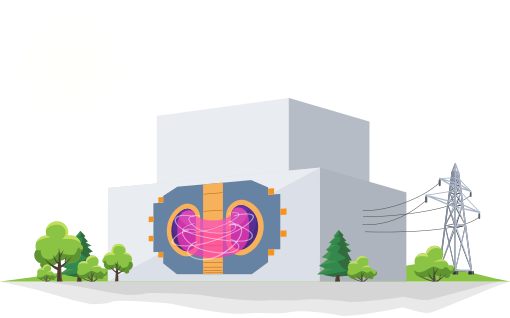
Inertial Confinement Fusion
16 min read · Energy Atlas Editorial
The inertial confinement fusion principle attempts to compress a small deuterium-tritium pellet to the density and temperature required for fusion ignition in its center. The reaction will then take place before the pellet remnants are blown apart, so the fusion plasma is held…
The inertial confinement fusion principle attempts to compress a small deuterium-tritium pellet to the density and temperature required for fusion ignition in its center. The reaction will then take place before the pellet remnants are blown apart, so the fusion plasma is held together by only its own inertia. There are two means of inertial confinement fusion. Direct drive, in which laser beams fall on the surface of the pellet, and indirect drive, in which laser beams generate strong X-ray radiation inside a cavity (hohlraum), and the X-rays compress the pellet. In December 2022, the laser-driven fusion facility NIF reached ignition, producing fifty percent more energy than was inserted.
Main Principles
There are three plasma parameters describing whether it could reach thermonuclear fusion: temperature, density, and confinement time. From the Lawson criterion, which combines them together, two major approaches to achieving fusion come out. The first is to keep plasma at a relatively low density (n ≈ 1020 m−3) and long confinement time (τ ≈ few seconds). This is done by magnetic confinement. The second method tries to keep plasma at a high density (n ≈ 1030 m−3) and very short confinement time (τ ≈ 10−10 s). This is called inertial confinement. The term "inertial" means that during fusion, nothing is holding particles in place. No magnetic cage, no holders. The fusion occurs so quickly that the particles will stay together only thanks to their inertia.
Compression
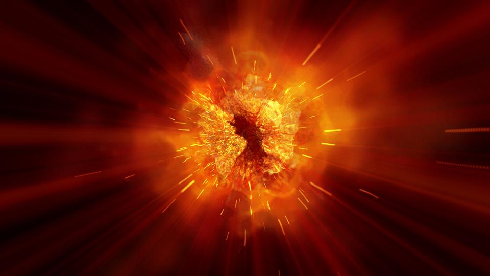
The idea of inertial fusion is very simple. If you compress a small amount of deuterium-tritium fuel into a very dense sphere, the compression process will heat the sphere interior to temperatures high enough for fusion to occur. The alpha particles arising from fusion will pass their energy to their neighbours, heating them up and enabling even more fusion reactions to take place. Plasma will begin to burn. In a very short time, the fuel is consumed and the rest of it is blown into space. The energy released by fusion in this brief moment could be tremendous.
Hydrogen Bomb
The first version of successful inertial fusion was the hydrogen bomb, where fusion fuel was compressed by a shock wave from surrounding fissile material. Although there were ideas on how to exploit its destructive potential for peaceful use, the hydrogen bomb was never found to be a good way to generate energy. Aside from military use, the amount of energy released from a hydrogen bomb is too large to be handled by any reasonable means.
Lasers
Another way to compress D-T fuel is the use of particle beams or powerful lasers. The vast majority of current research facilities use lasers with petawatt power. The laser beam is split into many beams focused on the target in the form of a pellet filled with deuterium and tritium. The lasers ablate the surface of the pellet, which causes a shock wave to travel inwards to compress the pellet interior. When the shock wave reaches the core of the pellet, the temperature and density are high enough to start the fusion. To improve the process, the energy delivery during the laser pulse is "shaped". It starts with relatively mild energy that starts the compression, then the sharp, powerful pulse induces a shock wave in the compressed material. The density in the core is around one-thousand times the density of water, or around 1,000 g/cm3.
Direct Drive
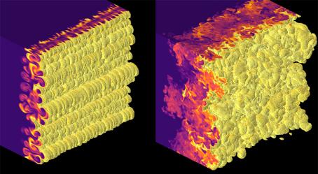
The method of simply firing lasers on the pellet surface is called direct drive. As the number of beams focused on the pellet surface is limited, there will inevitably be places where the pressure will be higher than elsewhere. Uneven compression will lead to Rayleigh-Taylor instabilities that will mix the pellet content. The core will not be compressed perfectly, and the fusion will not be ignited. Such a concept is very sensitive to laser focusing and pulse timing as well as the perfectly smooth shape of the fuel pellet, which is hard to achieve in practice.
Indirect Drive
Indirect drive partially solves the problem with symmetrical compression. In this approach, the pellet is suspended in the centre of a gold or lead cylinder called "hohlraum". The laser beams are not focused on the pellet but on the inner walls of the hohlraum instead. The walls irradiated by concentrated laser energy will start to produce intense X-ray radiation. X-rays fill the hohlraum and evaporate the peel of the pellet, which starts to move outward while the rest of it starts to move, thanks to the law of conservation of momentum, inwards, compressing the fuel. The compression is smoother in this concept, and the requirements for precision beam targeting and pellet manufacturing are less stringent, but the hohlraum heating consumes a significant amount of inserted energy.
The energy released in one "shot" could exceed one megajoule.
Repetition Rate
The repetition rate of inertial fusion confinement devices is very low. Before the new "shot", the reaction chamber has to be free from debris from the previous pellet, the laser entrance windows have to be perfectly clean and the new fuel pellet has to be positioned in the centre of the reaction chamber with nanometre precision. Most of the devices are able to do only one experiment per day.
Lasers
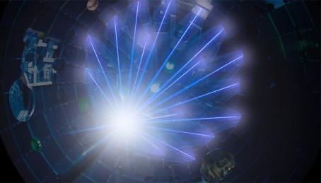
The devices compressing the target in inertial fusion are generally called drivers. In the early research, various types of drivers were considered, like heavy ion beams or X-rays from fission explosions. Since the laser's invention in 1960, the laser has been adopted as the most promising driver.
Laser Principle
The acronym "laser" stands for "light amplification by stimulated emission of radiation". It produces pulses of coherent light of one wavelength. During laser pulse formation, the flashes of "pumping" light excite electrons in the laser gain medium, e.g. neodymium-doped glass. When electrons are de-excited to their ground state, they emit photons of the same wavelength. A pulse of light is travelling back and forth through the laser medium, reflecting from mirrors on the ends, de-exciting electrons pumped by flashlamps and amplifying on each pass. After amplification, the beam can be sent via optical path wherever needed, focused on a target or modified in many ways.
Petawatt Lasers
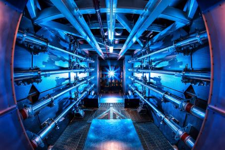
The present lasers used for inertial fusion are huge devices, occupying an area of about three football fields with power in the order of up to petawatts. Basically, they are a series of amplifiers in a row. At first, a weak laser pulse is created. Then it is amplified, split into more beams, amplified, and split again into many more beams, amplified again, and finally aimed at the target. The energy of a laser beam arises in a few millionths of a second from 1 billionth of a joule to several million joules. Usually, several dozens of beams are created during the amplification process, each with exactly the same energy, so they can symmetrically compress the target from many sides at once. The proper timing of a laser beam's arrival is ensured by its path length; as all the beams are travelling at exactly the same speed of light, the longer the optical path, the later the beam will arrive. With a precious set of mirrors and optical assemblies, the beams can be synchronized before entering the target chamber.
Energetic Electrons
The inertial fusion lasers are usually neodymium glass lasers that generate infrared light, but the fusion pellet is best compressed by ultraviolet light. This is because infrared light generates energetic electrons that penetrate the pellet surface (called an "ablator") and preheat the fuel, making it harder to compress. At ultraviolet wavelengths, energetic electron production occurs less. The laser wavelength is therefore converted to ultraviolet via final optics assemblies. Their task is also the final focus of the beam on the target.
Pulse Duration
The laser pulse duration varies between femtoseconds and nanoseconds depending on the experiment design. At the most powerful laser in the world, the National Ignition Facility, the laser has to travel about 1,500 metres from its origin to its destination on the target surface. Its journey takes only about 5 microseconds.
The inertial fusion lasers are very expensive devices, costing a few billions of dollars.
Target

The fuel for inertial fusion is deuterium and tritium. Both are isotopes of hydrogen. Deuterium is a stable isotope with one neutron and one proton in its nucleus, while tritium is a radioactive isotope with one proton and two neutrons. At room temperature, both are in the form of gas.
Capsule Structure
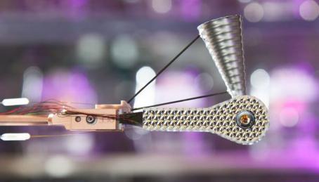
A special capsule is used to contain hydrogen so it can be used as a target for inertial fusion lasers. The surface of the target pellet can be made from various materials. The most common material is a thin plastic membrane (carbon hydrogen polymer), but glass or beryllium could also be used. The shell wall can have multiple layers and its thickness can vary from a few to several hundred micrometers. This target surface is called an "ablator" because it will be ablated during a laser pulse and its explosion compresses the content of the target. The surface of the ablator has to be extremely smooth. Any unevenness in the surface will result in asymmetric compression. The typical surface roughness must be less than 100 nanometres (10−7 m). By comparison, a human hair is more than a thousand times thicker. The typical size of the target pellet varies from around 0.5 mm to 5 mm in diameter and contains a few milligrams of fuel.
Filling
The fuel gas, typically a deuterium-tritium mixture or pure deuterium, is pumped under the ablator membrane. To ensure homogenous distribution of material, the pellet is then frozen and a thin layer of solid hydrogen is formed on the inner side of the ablator. The centre of the pellet contains hydrogen gas. To ensure a smooth surface, frozen deuterium fuel is irradiated by a low-power infrared laser. The mixture of deuterium and tritium is "self-smoothing" because of the small amount of heat generated by tritium decay. The composition and shape of the inner parts of the target are controlled by X-ray microscopy or even X-ray tomography to be sure that the target is as smooth and homogenous as possible. Before use, the target is stored under controlled conditions below zero to keep the fuel layer intact.
Hohlraum
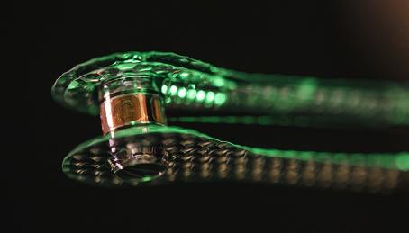
In the indirect drive method, the fuel pellet is placed inside a special metal cylinder called a hohlraum (cavity in German), made from lead, gold, or gold-coated uranium. Both ends of the hohlraum are open; here will enter laser beams aimed at the cylinder's inner walls. After an intensive laser pulse, the walls start to produce X-rays. As the hohlraum is effectively a resonant cavity, the X-rays will uniformly fill the cavity and symmetrically compress the target suspended in the hohlraum centre on plastic strings. The inner surface of hohlraum has to be as smooth as possible with a surface roughness of fewer than 100 nanometres. This places high demands on fabrication.
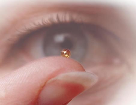
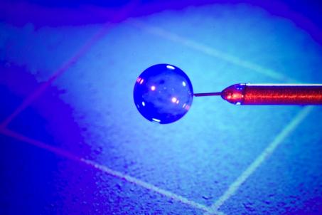
The position of the target in the centre of the chamber is also crucial and has to be perfect on a nanometre scale. The precise target handling system is used for control of its position and cooling it to around 18 kelvin.
The target capsule as well as the hohlraum are single-use devices. They will be destroyed by thermonuclear fusion energy, and for the next experiment, new ones have to be manufactured. The cost of one target is estimated to be around 2,500 USD.
Chamber
Structure
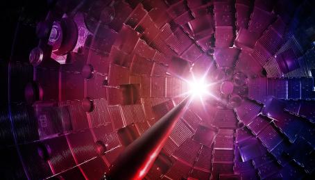
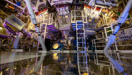
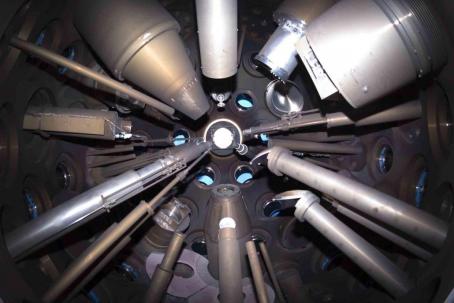
The inertial confinement fusion takes place in the centre of a large sphere about 10 metres in diameter. The chamber walls are made from aluminium panels several centimetres thick, covered with concrete. To serve as biological shielding, the concrete is injected with boron to absorb neutrons. The chamber is filled with holes that permit the laser beams to enter the chamber and provide ports for all necessary diagnostics and target handling systems. The windows for laser beams have to be kept perfectly clean so as not to disturb beam focusation. The various diagnostics watching target implosion and ongoing fusion reaction can peer through ports or be extended toward the target to observe the processes more closely. Inside the chamber, the vacuum is maintained. After every shot, the fusion products and debris arising from shattered pellets, hohlraum, and unfused material have to be evacuated.
Size
The huge size of the chamber, in comparison to the millimetre-sized fuel pellet, has several reasons. The energy released from a successfully compressed pellet could be substantial. If 1 mg of D-T fuel completely undergoes fusion, the released energy will be 340 MJ, which corresponds to the explosion of 75 kg of TNT. The average energy released during the present experiments is about 50 kJ. The remains of the pellet are scattered around at velocities many times exceeding the speed of sound. A smaller chamber could thus be damaged by a fusion explosion. The second reason is the number of laser beams entering the chamber together with diagnostics-there wouldn't be space in the smaller chamber for so many ports.
Inertial Fusion Power Plant
In the design of an inertial fusion power plant, the chamber has to be equipped with a cooling system that will lead the heat from the fusion reaction toward the steam generator and tritium breeder. Some designs came with the idea of liquid lithium running down the chamber walls. Lithium will absorb heat and neutrons, which will produce tritium, and also the constant flow will wash the walls of target remnants.
Most Important Inertial Fusion Facilities in the World

- LearningNuclear Fusion Courses
- Nuclear Energy Courses
- Renewable Energy Courses

- ITER Tokamak Interactive 3D Model
- Stellarator Interactive 3D Model
- ITER Tokamak and Stellarator Models for 3D Printing
- Thermonuclear Fusion
- Tokamaks
- Stellarators
- Inertial Confinement Fusion
- ITER
- History
- Thermonuclear Fusion Power Plant
- Nuclear Fusion Summary
- Nuclear Power Plant Interactive 3D Model
- Nuclear Power
- The Nuclear Power Industry
- Nuclear Fuel
- The Nuclear Reactors
- Radioactive Waste
- The Safety of Nuclear Power Plants




- Online 3D
- 3D Printing
- Images
- Videos
- Animations
- LearningNuclear Fusion CoursesHow Does Thermonuclear Fusion Work?
- Construction and Working Principle of Tokamaks
- Construction and Working Principle of Stellarator
- Inertial Confinement Fusion
- ITER — a Major Step Towards Thermonuclear Fusion
- Fusion Power Plant as a Clean Energy Source
- Basic principles
- Magnetic confinement
- Inertial and electrostatic confinement
- Summative, cross-sectional test — Light version
- Radioisotopes as Sources of Ionizing Radiation
- Interaction of Atomic Nuclei with Particles
- Nuclear Fuel and the Nuclear Fuel Cycle
- The Principles of Operating a Nuclear Power Plant
- The First Reactor and the First Nuclear Power Plant
- The Most Used Nuclear Reactors: PWR and BWR
- Sources, Processing, and Storage of Radioactive Waste
- Nuclear Power Plant Safety
- Nuclear fuel
- Nuclear fuel and nuclear reactors
- Nuclear power industry
- Nuclear reactors
- Radioactive waste
- Radioactive waste and safety of nuclear power plants
- Nuclear power
- Summative, cross-sectional test — Light version
- Summative, cross-sectional test — PRO version
- Types of RES and the Use of Renewable
- Comparison of Renewable Energy Source
- Characteristics of Hydropower
- Water Turbines in Hydroelectric Power Plants
- Wind Power Plants
- Solar Energy
- Solar Power Plants
- Biomass energy
- Geothermal energy
- Solar energy
- Water energy
- Wind energy
- ITER Tokamak Interactive 3D Model
- Stellarator Interactive 3D Model
- ITER Tokamak and Stellarator Models for 3D Printing
- Thermonuclear FusionWhy it Works?
- How it Works?
- Fusion Fuel
- Fusion in Stars
- Lawson Criterion
- Plasma
- How to Measure the Temperature in the Core of the Sun? or Diagnostics
- Artificial Fusion Principles
- Main Principles
- Material for Magnetic Coils
- Central Solenoid
- Toroidal Field
- Poloidal Field
- Vacuum Chamber
- Divertor
- External Heating
- Fuel
- Problems
- Most Important Tokamaks in the World
- Milestones
- Main Principles
- Magnetic Coils
- Vacuum Chamber
- Divertor
- Problems
- Most Important Stellarators in the World
- Milestones
- Main Principles
- Lasers
- Target
- Chamber
- Most Important Inertial Fusion Facilities in the World
- Milestones
- The Next Step on the Way Toward a Thermonuclear Fusion Power Plant
- Main Parameters
- Timeline
- Record Breakers
- Magnets
- Vacuum Vessel
- Blanket
- Divertor
- Cryostat
- Tritium Production
- Cooling
- Diagnostics
- External Heating
- The ITER Site
- Disruptions and Instabilities
- Early Fusion Research
- Thermonuclear Bomb
- Pinch
- Stellarator Concept
- Tokamak Invention
- Inertial Fusion Proposal
- ITER Organisation
- Fusion Today
- Clean Energy Source
- Dates and Locations
- Challenges
- Safety
- How it Will Look Like
- Fuel
- Waste
- Best Fusion Reactor for Power Plant
- Nuclear Power Plant Interactive 3D Model
- Nuclear PowerRadioactivity
- Ionising Radiation
- Natural Sources
- Man-made Sources
- Half-life
- Decay Series
- Quantities and Units
- Effects of Ionising Radiation
- Radiation Doses and Activities
- Nuclear Power Summary
- Principle of Operation
- Types of Nuclear Reactions
- Fission Chain Reaction
- Control and Reaction States
- Moderator
- Absorber
- Coolant
- Fission Products
- The Largest Nuclear Power Plants
- Fuel Production
- Fuel Enrichment
- Fuel Assembly
- Fuel Cycle
- Interim Storage
- Transportation
- Reprocessing
- Final Repositories
- The Nuclear Power Plant — How it Works
- The First Reactor
- Pressurized Water Reactor (PWR)
- Boiling Water Reactor (BWR)
- Heavy Water Reactor (PHWR)
- Gas-cooled Reactor (GCR) and Advanced Gas-cooled Reactor (AGR)
- RBMK Type Reactor
- High Temperature Reactor (HTGR)
- Reactor Using Fast Neutrons (FR)
- Small Modular Reactors
- The Future of Fission Reactors
- NPP PWR Interactive 3D Model
- NPP BWR Interactive 3D Model
- NPP Small Modular Reactors Interactive 3D Model
- AGR Reactor Interactive 3D Model
- CANDU Reactor Interactive 3D Model
- HTGR Reactor Interactive 3D Model
- Superphénix Interactive 3D Model
- Production of Radioactive Waste
- Types of Radioactive Waste
- The Processing of Radioactive Waste
- The Disposal of Radioactive Waste
- Nuclear Safety
- Safety Systems
- External Hazards
- INES Scale
- Nuclear Accidents
- International Nuclear Organizations
- Nuclear Power Plants and the Environment
- WATER energyHydroelectric Power Plant Interactive 3D Model
- The Physical Properties of Water
- The Origin of Water Energy
- History of Water Energy Utilization
- Water Energy and Its Uses
- Dams and Reservoirs
- The Highest Dams and Largest Reservoirs
- The Segner Wheel
- Francis Turbine
- Kaplan Turbine
- Pelton Turbine
- Choosing a turbine (Turbine selection graph)
- Hydroelectric Power Plant Operating Principles
- Types of Hydroelectric Power Plants
- The Largest Hydroelectric Power Plants in the World
- Tidal Energy and Sea Wave Power
- Marine Current Power and Ocean Thermal Energy
- Environmental Impact of Hydropower
- Wind Turbine Interactive 3D Model
- The Energy of Flowing Air
- The Beaufort Wind Force Scale
- The History of Wind Power Utilization
- Wind Power Plants
- Wind Turbine and its Working Principle
- The Largest Wind Farms
- Types of Wind Turbines
- Wind Turbines and the Environment
- Solar Power Plant Interactive 3D Model
- Solar Rays Energy
- Ways to Use Solar Heat
- Solar Collectors
- Solar Concentrators
- Central Tower Solar Power Plants
- Solar Farms
- The Largest Solar Power Plants
- The Energy Use of the Photovoltaic Effect
- Photovoltaic Farms
- Solar Energy and the Environment
- Solar Energy and Solar Power Systems Summary
- Hot Dry Rock (HDR) Geothermal Energy Interactive 3D Model
- Heat from the Earth’s Core
- Geothermal Phenomena
- Mankind and the Energy from the Earth
- Geothermal Systems
- Geothermal Power Plant
- Environmental Impact
- Biomass Energy Interactive 3D Model
- Biomass
- Types and Processing of Biomass
- Available Technology of Biomass
- Biofuels
- Biomass Power Plants
- Biomass and the Environment
- Rapid development of energy consumption
- The Future of Solar Energy
- The Future of Hydro Energy
- The Future of Renewable Energy Sources
- Development of Renewable Sources
- Online 3D
- 3D Printing
- Images
- Videos
- Animations
- Glossary
- Log-in
- Create new account
- ITER Tokamak Interactive 3D Model
- Stellarator Interactive 3D Model
- ITER Tokamak and Stellarator Models for 3D Printing
- Thermonuclear Fusion
- Tokamaks
- Stellarators
- Inertial Confinement FusionMain Principles
- Lasers
- Target
- Chamber
- Most Important Inertial Fusion Facilities in the World
- Milestones
- Glossary

The inertial fusion facilities are located in the United States (NIF and OMEGA EP), the United Kingdom (ORION), France (Laser Megajoule), Japan (LFEX), and China (Shenguang III).
National Ignition Facility (NIF)
The National Ignition Facility (NIF), located at Lawrence Livermore National Laboratory near San Francisco, USA, hosts the world's biggest and most precise laser system. Its 192 laser beams could deliver more than 2 million joules of ultraviolet energy to the peppercorn-size target in a billionth-of-a-second long pulse. The peak power is up to 500 terawatts. The laser amplifiers are located in a ten-story building on an area of about three football fields. From its origin to the destination in the centre of the target chamber, the laser has to travel about 1,500 meters. The journey takes only around 5 microseconds. The NIF specialises in indirect fusion, where lasers fire into the interior of a cylinder called hohlraum. It starts to produce X-rays that compress the fuel pellet placed in the centre of the cylinder. NIF was built in 2002, reached full operation in 2010, and is capable of about 300 shots per year.
In August 2021, NIF achieved 1.35 MJ of fusion energy output, breaking the previous record held by tokamaks. The important goal of fusion research, the ignition state in which more energy is released by fusion than is inserted, was reached by NIF in December 2022 by releasing 3.15 MJ.
OMEGA
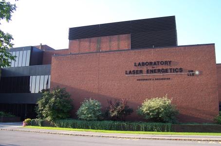
The Laboratory for Laser Energetics of the University of Rochester, located in Brighton, New York, USA, operates OMEGA and OMEGA EP lasers. OMEGA was built first and in 1995 became the world's highest energy ultraviolet laser. Its 60 beams are able to deliver 40 kilojoules at up to 60 terawatts. The maximum fusion yield of OMEGA so far is about 1014 neutrons per shot, and it once held the record for the highest neutron yield of any inertial confinement fusion device.
The neodymium-doped glass laser OMEGA EP (EP stands for Extended Performance) equipped with four independently configurable beamlines was finished in 2008. Each of its beams can deliver 0.5 terawatts of energy. Two of them can be compressed for short-pulse operation, and the combination of short and long pulses provides high variability in experiments. The research facility specialises in direct drive fusion, trying to compress the fuel capsule without using hohlraum. The device is capable of 7 to 8 shots per day.
Laser Megajoule
A Laser Megajoule is a research device located near Bordeaux, France. As its name suggests, it is able to deliver 1.4 megajoules of energy to its target. The peak power of its 176 beamlines is up to 400 terawatts. This enormous power is aimed at a small target in the rugby-shaped hohlraum as this device focuses on indirect drive. The laser serves not only for thermonuclear fusion but also for astronomy, planetology, medicine, and also for military purposes. The device started operation in October 2014 and experienced its first fusion in 2019. Later, another laser named PETAL with petawatt power was built and started operation in 2017.
Milestones
Thermonuclear Bomb
For the inertially confined thermonuclear fusion applies the same as for fission-the first time it was ignited, it was misused for military purposes. The hydrogen bombs, detonated in 1952 and 1953 by America and Russia, may be considered a successful demonstration of inertial confinement. The deuterium-tritium reaction was ignited by the explosion of surrounding fissile material. Although there were attempts to invent how to use such power for peaceful purposes like heating water in an underground cavern, mining, or hydraulic fracking, it was never implemented in praxis.
The idea of small fusion explosions was interesting not only for energetics but also for the military because it could simulate processes in the core of a hydrogen bomb without having to detonate any. The research was therefore financed by all governments interested in hydrogen bomb development. The source of clean energy was only in second place.
Lasers
A variety of drivers that could cause fuel pellet compression were considered, including pulsed power machines, charged particle accelerators, plasma guns, and hypervelocity pellet guns. After the first laser was constructed in 1960, it appeared as the best possible driver for inertial fusion. In 1971, the Russian Kalmar laser, an Nd-glass device with 9 beams and 100 J of delivered energy, compressed D-T target and ignited fusion reaction, proved this method to be usable.
Indirect Drive
Lawrence Livermore National Laboratory built several lasers (Janus, Argus, Cyclops) and started the first experiments with indirect drive in 1976. The hohlraum cavity filled with X-rays simulated the situation in a hydrogen bomb well and was reaching smoother compression.
The powerful Shiva laser from Lawrence Livermore National Laboratory was completed in 1977, and its 20 beams were able to deliver 10 kJ of infrared light. Even with this power, it was not enough for breakeven; still less energy was gained than inserted into the target. The Rayleigh-Taylor instabilities resulting from uneven compression mix the cool and hot parts of the target, reducing fusion output. Also, energetic electrons that heat the target content prematurely, complicated the compression. This problem was solved in 1980 by the idea of transforming infrared light into ultraviolet. When irradiated by an ultraviolet laser, the generation of energetic electrons in the target was substantially reduced.
Fast Ignition Approach
In 1994, the method of fast ignition appeared. By this technique, the target material, already compressed by a nanosecond long pulse, is ignited by a powerful pico-second pulse of another laser aimed directly at the target core.
Ignition
The construction of the most powerful inertial fusion laser started at Lawrence Livermore National Laboratory in 1997. The National Ignition Facility reached full capacity in 2010, delivering more than 1 megajoule at the target with its 192 beams. In 2018, NIF achieved a record fusion output of 54 kJ and broke its own record in 2021 with a 1.3 MJ fusion power output, which represented 70% of the laser energy input. NIF claims to have reached a burning plasma state in 2022; the heat produced by the resulting alpha particles was a major source of heating for the ongoing fusion reaction. And finally, ignition was reached in an experiment conducted on December 5, 2022. The shot produces 3.15 MJ of fusion energy, more than the energy of the lasers compressing the target. For the first time in fusion research history, the fusion reaction produces more energy than was needed for its creation.
Keep reading
Articles
How it Works?
In normal conditions, atom nuclei don't fuse spontaneously. The nucleus is positively charged and electrostatic forces will repel each other long before they come so close that strong nuclear forces can start to act and bind nuclei together.
5 min read
Lawson Criterion
John D. Lawson wondered what conditions need to be fulfilled in order to get enough energy from a fusion reaction to use it in a power plant.
5 min read
Questions
What is the difference between fusion and fission?
Fission splits heavy nuclei. Fusion joins light ones. Both can release binding energy; only fission is commercial electricity today.